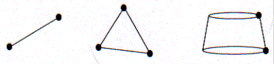
The representation of the boundary by a set of characteristic panels enables us to easily define the boundary using a data structure. For example an ordered list of the coordinates of the vertices of the approximating polygon in Figure 2.1 defines the boundary. As an illustration, the boundaries of the test problems are explicitly stated in this manual. The characteristic panels that are used in 2D, 3D and axisymmetric problems are illustrated in Figure 2.2.
Part of the numerical error in the boundary element solution will be a result of the approximation of the boundary. A better boundary approximation and a smaller numerical error will generally arise if the boundary is represented by curved panels. The methods described in this work apply to only the simplest panels, straight line panels for two-dimensional boundaries, planar triangles for general three-dimensional boundaries and truncated conical panels for axisymmetric problems, as shown in Figure 3.2. In this manual we consider the representation of the boundary S in terms of these panels in each dimensional space. The boundary can be expressed by two data structures in each case; the first enumerating the vertices and storing their coordinates, the second lists the individual panel by indicating the two or three vertices that define each panel.